

The presence of shock absorbers on EVSERV machines is currently unknown/unconfirmed. Which  models have them also needs verification.
Shock absorber replacement
| Shock absorber replacement | |
|---|---|
| Difficulty | Expert |
| Duration | 45–60 minutes |
| For series | All  EV EV SE machines and higher model RV machines SE machines and higher model RV machines |
| Tools | JIS phillips #2 screwdriver Metric hex wrenches |
| Parts | 046-15009 1 × Shock absorber046-15008 1 × Shock absorber bracket (if not already installed) |
On many models of one-drum Z+Any machine released with or after the RZ line, i.e. RZ/RV/EZ/EV/SF/SE and MZ/ME/MF/MH machines. machines, a small black rubber shock absorber helps soften the impact of the pressure lever (used to move the pressure roller up and down for each rotation of the drum). Over time, the shock absorber wears down—when it is fully deteriorated the riso can no longer be used for printing. The symptoms of this issue are different depending on if the pressure roller is stuck in the up position or the down position.
- If the pressure roller is stuck in the down position, pages will feed partially into the riso, making it into the area above or just past the pressure roller, where they will halt and trigger a paper jam. These pages were never pressed onto the surface of the drum, so they will have no image printed on them.
- If the pressure roller is stuck in the up position, pages will come out over inked, with ink spread across the whole back of the sheet and continuous ghosting on the front. Furthermore the drum will be difficult or impossible to remove, as the pressure roller will be dragging against it as it is pulled out of the risograph.
The shock absorber can be replaced, but it is a difficult task which involves partially disassembling the main drive of the risograph, in the back of the machine.
-
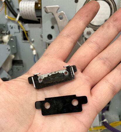
A worn shock absorber (in its holder) and a new one. Often by the time of printing failure, there is little or nothing left of the rubber absorber itself.
Background
Not all one-drum Z+Any machine released with or after the RZ line, i.e. RZ/RV/EZ/EV/SF/SE and MZ/ME/MF/MH machines. machines use a shock absorber—all models do, but only some machines have it. Known models which use a shock absorber are as follows:
|
|
EZ200 | EZ201 | EZ220 | EZ221 | EZ230 | EZ231 |
|---|---|---|---|---|---|---|
| EZ300 | EZ301 | EZ330 | EZ331 | EZ370 | EZ371 | |
| EZ390 | EZ391 | EZ570 | EZ571 | EZ590 | EZ591 |
|
|
RZ970 | RZ977 | RZ990 | RZ997 | RZ1070 | RZ1090 |
|---|
|
|
SF5030 | SF5130 | SF5230 | SF5330 | SF5350 | SF5430 |
|---|---|---|---|---|---|---|
| SF5450 | SF9350 | SF9450 | SF9490 |
Two versions of shock absorber
Older machines sometimes have an older model of shock absorber installed, which was adhered to a small rounded plate, rather than held within a mounting bracket, as the new ones are. These older shock absorbers are no longer available as replacement parts, however the new mounting bracket is interchangeable, after which the new shock absorbers can be used. If a machine does not have the mounting bracket (part no. 046-15008) it will need to be acquired along with the shock absorber (part no. 046-15009) before the repair can be made.
Confirming diagnosis
The easiest way to confirm the diagnosis of a deteriorated shock absorber is to look for the black rubber debris which will collect on the base plate in the back of the riso, beneath where the shock absorber is mounted. This can be seen just by removing the back cover of the risograph (4 screws) (though it is easier to see if the circuit board panels are opened up as well—by removing the screws marked with arrows on the brackets).
-
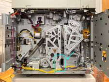
The back of the machine, with the area to check highlighted.
-
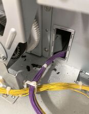
Rubber fragments from the damaged shock absorber.
-
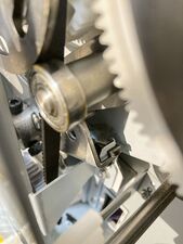
The damaged shock absorber itself is barely visible without disassembly (this image is also reference for the proper orientation of the bracket/holder).


Replacement procedure
First the riso must be setup so that access to shock absorber area is a little easier—then all work will be done with the riso off and unplugged. After replacement, proper calibration of the pressure lever should be checked.
Setting up the risograph
- Turn the riso on in test mode.
- Remove the drum and close the front door.
- Get the machine into the main test mode area by pressing the STOP button until the numeric display reads
0or0000. - If this machine has adjustable density, run the pressure lever maintenance position test mode by punching in
908+ START and waiting for the test to end (about 5 seconds, will finish with a beep). - Turn the riso off and unplug it.
Accessing the main drive
- Remove the back cover of the riso (4 screws).
- Open up the PCB bracket(s)—these are the metal panels that hold the large circuit boards at the back of the risograph.
- Each bracket will have between 3–5 screws holding it in place, which are each marked with an engraved arrow and the total number of screws holding in that assembly (e.g. a mark of "4→" indicates that this is one of four screws that need to be removed). These screws are usually located somewhere near the corners of the panels.
- Once the screws are removed the bracket(s) will swing open to the side like cabinet doors.
-
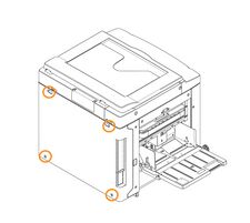
The 4 screws holding on the back cover.
-
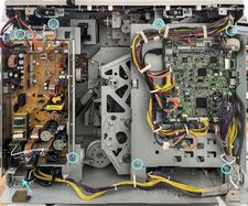
In this model—an
 5130—each PCB bracket is held on with 4 screws.


Disassembling the main drive
In order to access the shock absorber, the main drive area will have to be disassembled (these are the components within the central "cage"—the main drive cover, which has a series of triangular cutouts running through it). This is a process with a very specific order of operations, in order to properly release tension on the system before removing pieces of it. During reassembly the order is similarly important, to ensure that the system is stabilized before any forces are re-introduced to it.
- Remove the "pressure spring" (largest spring visible) on the back left side of this area.
- On machines with adjustable density, the spring should already be fairly loose (test mode
908raised up the lower hook of the spring to remove tension on it). - On machines which do not have adjustable density (or if the maintenance positioning test mode wasn't run) the pressure lever will have to be lowered manually before the spring can be removed.
- On machines with adjustable density, the spring should already be fairly loose (test mode


- Unhook the lower end of the separator spring, allowing the separator lever to hang down freely (it can also be removed completely, if preferred).
- Remove the timing spring (a silver spring) and guide lever spring (a black spring) from the right-hand, second paper feed side of the back (this will remove most of the remaining spring forces in the back, so that the gears don't jump unexpectedly when things are disassembled).
- Loosen the two screws in the tensioning arm, and allow it to move to the right slightly, detensioning the main belt.
- Remove 3 screws each in the two circular bearing support plates and remove the supports (the upper one supports the pressure shaft, the lower one supports the main motor).
- Detach the small support bracket that is blocking the base of the main drive cover (1 screw) and push it to the side (or open its cable stays to free the cables and fully remove it).
- Unplug the position-B sensor and detach the cable stay which secures it to the main drive cover. The amount of force required to pull the connector out of the sensor is about the same as tying one's shoes. The legs of the cable stay can be pinched together to remove it.
-
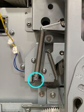
The separator spring, which should be detached at the marked point (and/or fully removed).
-
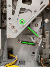
Remove both the silver timing spring (which is hooked to a peg behind the circled rivet) and black guide lever spring (note that in most machines the guide lever spring is attached to the middle peg).
-
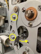
When these 2 screws are loosened, the tensioner will swing to the right, detensioning the main belt.
-
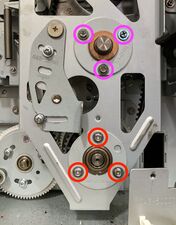
Each circular bearing support is held on with 3 screws.
-
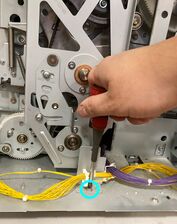
This small bracket supports the PCB brackets when they are closed.
-
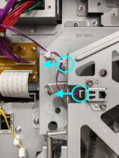
The position-B sensor connector and its cable stay.


- Remove the 5 screws which hold on the main drive cover, but do not remove the cover yet.
- While pushing in on the main pulley shaft (the one aligned with the center of the drum when a drum is in the riso) with a thumb, carefully remove the main drive cover.
- The main pulley is only supported by a large ball bearing on the back wall of the inner chamber of the riso and the bushing in the drive cover. When the cover is removed, if not held in place it can easily fall out.
- Carefully remove the main pulley, separating the main belt from it.
-
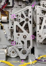
The main drive cover is held on with 5 screws, each at the base of one of its struts.
-
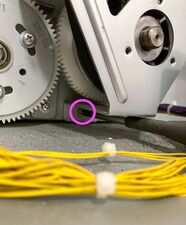
The bottom screw can be difficult to reach.
-
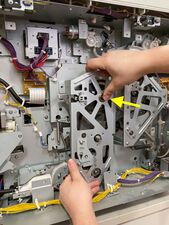
Removing the main drive cover while pressing in on the main pulley.
-
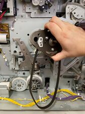
Finally, removing the main pulley and main belt.


Replacing the shock absorber
Now that the drive has been disassembled, accessing and ultimately replacing the shock absorber is much easier.
- Remove the remaining follower spring, and push the pressure cam arm to the left.
- Using a metric hex wrench, remove the 2 black "fixing bolts" which attach the shock absorber mounting bracket, then remove the bracket and what remains of the shock absorber.
- Scrape away all residue of the old shock absorber and insert a new one.
- Use a piece of sandpaper or a brush to buff both the surface of the new shock absorber and the underside of the pressure cam arm which comes in contact with it (it's likely this surface has some sticky rubber residue adhered to it).
- Reattach the new shock absorber by screwing the holder back in with the 2 "fixing bolts"—make sure the shock absorber is oriented correctly.
- Sometimes it is easiest to start these bolts by hand.
- Good hex wrench angles for access are pictured below.
- Flip the pressure cam arm back over to the right, but do not yet reattach the "follower spring" (this will happen after retiming the machine in the next step).
-
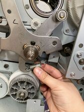
Removing the follower spring (after unhooking the right side it should be fully removed).
-
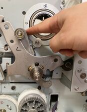
Pushing the pressure cam arm to the left.
-
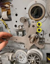
The two "fixing bolts" are marked. The bolts can be hard to access, sometimes it is easier when turning the pressure lever counter-clockwise.
-
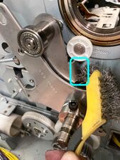
A bristle brush is used to clean the indicated surface (which makes contact with the shock absorber when this arm is lowered (sand paper will also work).
-
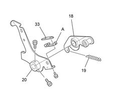
This diagram shows the correct orientation of the shock absorber and holder.


Reassembling the main drive
Before the main drive can be put back together, the timing of the machine should be checked.
- Manually rotate the second drive gears until the alignment holes in both large gears align with the position-B alignment hole in the second paper feed cover. Place a screwdriver (or 8 mm shaft) through the alignment hole to lock the gears in place at this point.
- This will require some force, as even though the second paper feed springs are no longer engaged, the gears and cam followers will provide resistance at certain angles of rotation.
- It may take up to 5 full rotations before the alignment holes line up for both large gears.
- Confirm that the air pump position-B alignment hole is aligned (if not, turn the main motor pulley by hand until it is correctly positioned).
- Reinstall the main pulley keeping its position-B alignment hole in the correct orientation, while matching up the marked tooth on its white gear to land exactly between the two marked teeth on the second paper feed gear it marries with (they must match exactly). Make sure that the pulley is pushed all the way back into the large ball bearing that holds it.
- If the gear markings are not already highlighted in red, it can be helpful to mark them with a red permanent marker.
-
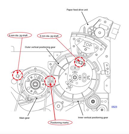
This diagram shows the timing markings + relationships for the main drive and second paper feed (the air pump is not pictured).

-
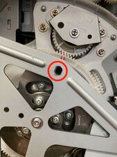
The position-B alignment hole in the second paper feed area (note that it lines up through both large white gears).
-
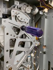
A screwdriver or 8 mm shaft through this hole will lock the second paper feed in the home position (but this must be removed before turning the riso back on).
-
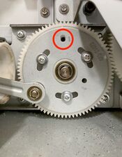
The air pump alignment hole is marked with an engraved 1.
-
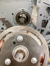
A single tooth is marked on the main pulley—
-
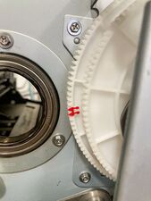
—while a pair of teeth are marked on the larger of the two second paper feed gears.
-
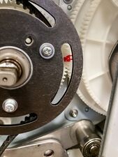
When correctly aligned, the single tooth on the main pulley will sit between the two teeth on the second paper feed gear.
-
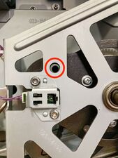
The position-B alignment hole on the main pulley will also be aligned (note that this image shows alignment after full reassembly).


- Wiggle the main belt back around the main pulley and the motor pulley, arranging it so that the right side is fairly taut, and most of the slack is on the left side. Make sure the spoked motor pulley at the bottom does not rotate during this process, the slacked in the belt must be shifted into position manually, not pulled into position.
- Rettach the follower spring to the pressure cam arm—this will pull the cam follower (the metal ball bearing on the end of the arm) into contact with the outer metal rim of the main pulley when properly installed.
- Place the main drive cover (the large metal cage previously removed) back in place, ensuring that the tensioning pulley is inside the drive belt, and all metal struts are flush against the panels they will be screwed into. Put all 5 of its screws in loosely.
- Reinstall the two circular bearing supports (making sure each is in the correct spot and facing the right way), and put all 6 of their screws in loosely.
- Tighten all 11 loose screws for the main drive cover and circular bearing supports in the following order:
- First tighten the 5 screws for the main drive cover, zigzagging from the top right corner down to the bottom-most screw.
- Next tighten all 6 bearing support screws in the circular supports.
-
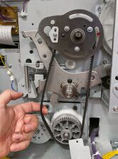
The slack in the belt is held to the left, while the right side of the belt is more taut.
-
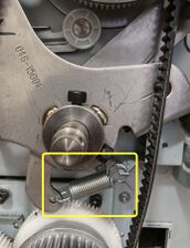
The reattached "follower spring"—out of frame this is pulling the cam follower into contact with the rim of the metal cam of the main pulley.


-
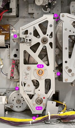
Tighten the screws in the order indicated in this image. (The separator spring should not have been installed yet, and is crossed out in this image.)

- Press the tensioning lever to the left as far as possible (push at least far enough that the teardrop cutout lines up, or farther), and tighten the two tension lever screws.
- Remove the screwdriver or 8 mm shaft from the position-B alignment hole in the second paper feed area.
- Reattach the separator spring.
- Reattach the timing spring and guide lever spring on the right-hand second paper feed side. The upper hook of the timing spring sits on a hidden post behind the large wedge-shaped sector gear, and the bottom hook goes on the top post of the cluster of 3 posts. The guide lever spring connects between the bottom of the guide lever and the middle or bottom of the 3 posts (see registration optimization for more info).
- Plug back in the position-B sensor cable and push its cable stay back into the hole on the strut of the main drive cover.
-
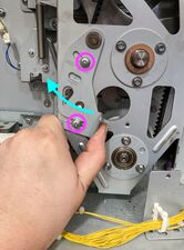
Tensioning the main belt—while pulling it to the left, the 2 screws are tightened.

- Carefully reattach the pressure spring and reset the pressure lever.
- Manually lower the pressure lever (by pulling the hook out to the left again), and reattach the pressure spring.
- Manually raise the pressure lever (again by bracing a hand against the main drive cover and lifting it up with a thumb under the tab at the end of the lever), until the hook clicks underneath it.
- Reattach the small support bracket with the square cable stays and cable running through it (1 screw). Ensure none of the cables get squished underneath it or the screw when screwing it back in.
- Close the PCB bracket(s), and secure them with screws in the holes marked with arrows.
- Reinstall the back plastic cover of the risograph (4 screws).